Page 985 - MISUMI SINGAPORE Economy Series
P. 985

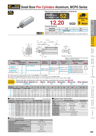
Small Bore Pen Cylinders Aluminum, MCPG Series


           New                                   Representative model: E-MCPGS6-5-TM-NB-NR-NS
          Products
                                                  Save Up to
                                                  vs Standard Type  52%              Shipping
                                                                                        from
 14                                                    12.20               SGD 9 days              14
 Air Cylinders / Valves / Regulators /   Shock Absorbers / O-Rings  Volume Discount  Unit Price  20%  Shock Absorbers / O-Rings  Air Cylinders / Valves / Regulators /

                                                                       1~9
                                                                                       10~
                                                      Quantity
                                                      Discount
                                                 E  Shipping days may differ by Quantity.
                                                 E Quantity of volume discount above is for representative Part No. It may differ by the Part.
 Cylinders and   Accessories                 AB   A+Stroke AC+Stroke                               Accessories  Cylinders and


 P.951                         G F         DA  MA  PA  2-P   PB        DA                          P.951
                                           EA                          30°
                                        FA
 Shock   Absorber        C  CA          E                           φD                             Absorber  Shock


 P.991                     R    B           M    GA                Threadless Piston Rod           P.991
                                                                       Material:  Cylinder Block Material Aluminum Alloy
                                                                       Surface Treatment: Anodized
 Rod End   Bearings  1Type  2Cylinder   3Stroke (mm)  Rod End  Method* 1  6Rod End   Magnetic Switch* 3 8Quantity  Bearings  Rod End
               Part Number
                                                        5Fixing
                                              4Piston
                                                                   Joint*
                                                                                7Type
                                                                       2
                        6
 P.999    (Without Magnetic Ring)  I.D. (mm)  5 10 15 20 25  TM(Male Thread)  NB(Without Bracket) NR(Without Joint)  NS(Without Magnetic Switch)   (With NS   P.999
           E-MCPG
                        8
                                                                          CHM(Reed Magnetic Switch)  Type, no need
 Floating Joint  (With Magnetic Ring)  10  5 10 15 20 25 30 35 40  TN(Threadless)  FB(Foot Bracket)  SJ(Single Clevis Joint) DHM(Electronic Magnetic Switch-2-Wire Type)  to specify Qty)   Floating Joint
           E-MCPGS
                                                                                             1
                                                                 DJ(Double Clevis Joint) DHN(Electronic Magnetic Switch-3-Wire NPN Type)
                                                      FR(Flange)
                        12
                                                                          DHP(Electronic Magnetic Switch-3-Wire PNP Type)
                                                                                             2
                        16
 P.1004   E(*1) References for fixing accessories: FB (Foot Bracket)P.982, FR (Flange)P.984        P.1004
          E(*2) Piston rod end threadless type, rod end joint are not provided. For rod end joint, refer to P.1003~P.1004.
          E(*3) Magnetic switch is not available for cylinder without magnetic ring. The magnetic switch has a 2-meter long wire. Refer to P.990.
 Silencer  Ordering  Please order after selecting part number and parameters according to the selection steps 1 to 8.  -  NS  Silencer
                                           - 3Stroke - 4Piston Rod End - 5Fixing Method - 6Rod End Joint - 7Type · 8Quantity
                   Part Number (1Type · 2Cylinder I.D.)
          Example
                          E-MCPGS6
                                                                  NB
                                                                        -
                                                             -
                                           -
                                              5
                                                   -
                                                                             NR
                                                       TM
 P.1006   Cylinder   A  AB   AC    B  C  CA  D  DA  E    EA  F  FA  G  GA  M  MA   P   PA  PB  R   P.1006
          I.D. (mm) Non-magnetized  Magnetized  17  Non-magnetized  Magnetized  14  16.5  6  3  9  M3×0.5  7  5.5  2.4  13  4  M10×1.0  8  M3×0.5  5.5  6.5  2
 Control Valves   and Accessories  10 8  39.5  44.5  20  19.5  24.5  14.5 17.5  8.5  4 4 6  12  M4×0.7  10  7 7 8  3 3 3  17  4 4 4  M12×1.0  10  M3×0.5  6.5  7.5  2.5  and Accessories  Control Valves
            6
                    38
                 33
                            16
                                21
                                          7
                            18
                                23
                                                                                              2
                                                                               8
                    43
                                                                                           7
                                                                                        6
                 38
                                                         10
                                   15
                                                                                        6
                                      19
                                                                  17
                                                12
                                                                                  M3×0.5
                        20
                                                                        M12×1.0
                                          7
                                                                                           7
                                                                               8
                                                   M4×0.7
            12
                                                         12
                                      21.5
                                                                                             2.5
                                                14
                                                   M5×0.8
                                                                  19
                        24
                    48.5
                           19.5
                                                                        M14×1.0
                               24.5
                                                                                  M5×0.8
                43.5
                                   17
 P.1007     16  43.5  48.5  24  19.5  24.5  20  24.5  10  6  14  M5×0.8  12  8  3  19  4  M14×1.0  10  M5×0.8  6.5  7.5  3  P.1007
          QCylinder Theoretical Output Force Table   Unit:  Newton (N)  QMagnetic Switch Specification
 Air Source   Handling  Cylinder  Piston  Operating   Compression area   0.1  0.2  Air pressure (MPa)  17.0  19.8  Item  10V~28V DC  5V~30V DC  5V~240V AC/DC  Handling  Air Source
                                                                                       Reed Sensor
                                                                      Electronic Sensor
                   Type
                         (mm 2 )
          I.D. (mm) Rod O.D.
                                     0.3
                                             0.5
                                                                  2-Wire Type NPN 3-Wire Type PNP 3-Wire Type
                                                 0.6
                                                         Type
                                                                                       2-Wire Type
                                                     0.7
                                         0.4
                        28.3
                                            14.2
                             2.8
                                     8.5
                  Double  Push
                                        11.3
                                 5.7
                                                         Voltage
           6
               3
                  Acting Pull
                                 4.2
                                     6.4
                                         8.5
                                                                                        100mA
                                                    35.2
                             5.0
                                            25.2
                                                30.2
                        50.3
                                                         Max. Contact Capacity
                                                                            6W Max.
                                                                  2.8W Max.
 P.1015    8   4  Double  Push  21.2  2.1  10.1  15.1  20.1  10.6  12.7  14.8  Max. Switching Current 2.5mA~100mA  30/200mA Max.  10W Max.  P.1015
                  Acting Pull
                        37.7
                             3.8
                                    11.3
                                 7.5
                                        15.1
                                            18.9
                                                    26.4
                                                22.6
                                                                            5mA Max.
           10  4  Double  Push  78.5  7.9  15.7  23.6  31.4  39.3  47.1  55.0  Internal Consumption Current  3mA Max.  0.01mA Max.  - -
                                                         Leakage Current 0.05mA Max.
                  Acting Pull
                                                39.5
                             6.6
                                        26.4
                                13.2
                        58.9
                                    19.8
                                            33.0
                                                    46.1
 O-Rings   12  6 6  Double  Push 113.0  11.3  22.6  33.9  45.2  100.5 120.6  140.7  Protection Circuit Power polarity reverse protection, surge absorption protection  -  O-Rings
                                                67.8
                                                    79.1
                                            56.5
                  Acting Pull
                        84.7
                                                50.8
                                        33.9
                                    25.4
                                            42.4
                                                    59.3
                             8.5
                                17.0
                                                         Operating Temperature
                                                                             -10°C~70°C
                                40.2
                                        80.4
                            20.1
                  Double  Push 201.0
                                    60.3
           16
                                                                             General IP64
                                                         Protection Rating
                  Acting Pull 172.7
 P.1027   QCylinder Specifications  17.3  34.5  51.8  69.1  86.4 103.6  120.9                      P.1027
                 Cylinder I.D. (mm)          6~16
          Operating Type                  Double Acting
          Fluid Used              Air (filtered through the filter screen of 40 μm)
          Operating Pressure Range Mpa(psi)  0.15~0.7 (22~100)
          Guaranteed Pressure Resistance Mpa(psi)  1.2(175)
          Operating Temperature °C          -20~70
          Operating Speed Range mm/s        50~500
          Cushion Mechanism               Without Cushion                                         980
   980   981   982   983   984   985   986   987   988   989   990