
Page 211 - MISUMI SINGAPORE Economy Series
P. 211
1 1
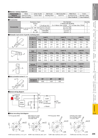
Ball Screws / Lead Screws / Actuators QMaterial / Surface Treatment Carbon Steel Bearing Steel Ball Screw Nut Aluminum Alloy Aluminum Alloy Lead Screws / Actuators Ball Screws /
Slide Block
Ball Screw
Components
Cover
Linear Guide
Body
Aluminum Alloy
Material
SCM415
Clear Anodized
Surface Treatment
Clear Anodized
-
-
Clear Anodized
-
Rolled Ball Screws QAccessories Accessory Name Screw End Timing Pulley 10×14 Motor Side (400W) 17×19 Motor Side (750W) Quantity Screws Rolled Ball
Part Number
Sensor
3
C-MSX672N-2M(NPN)
BC
1
Coupling (mm)
5GT-25 Teeth
1
Accessories
method
P.37 Motor connection BL / BR / BM Motor End Timing Pulley 5GT-25 Teeth 1 1 1 P.37
Timing Belt
BM
315-5GT-15
Precision Ball Screws QAllowable load center of gravity overhang (mm) Lead 5 Lead 10 Lead 20 Screws Precision Ball
BL / BR
Timing Belt
385-5GT-15
A
Horizontal
P.59 Installation 70kg 90kg 120kg 65kg 85kg 110kg 35kg 55kg 75kg P.59
1850
3235
1666
Support Units for Ball Screw B C B 349 263 187 338 248 182 547 331 231 for Ball Screw Support Units
1911
733
1030
1445
2482
1102
A
276
373
217
408
306
230
202
328
C
538
P.81 Wall Lead 5 Lead 10 Lead 20 P.81
Installation 75kg 95kg 120kg 60kg 80kg 110kg 30kg 50kg 75kg
B
Motor Brackets A A 377 288 218 408 296 202 633 365 230 Brackets Motor
231
187
266
368
369
182
246
B
322
644
C C 2988 2333 1850 2092 1554 1102 1961 1143 733
P.91 Lead 5 Lead 10 Lead 20 P.91
Lead Screws C Installation 20kg 30kg 40kg 15kg 25kg 30kg 10kg 14kg - - Lead Screws
Vertical
1377
970
808
1922
A
911
1368
1618
683
P.93 A C 1368 911 683 1618 970 808 1922 1377 - P.93
Lead Screw Nuts QStatic allowable moment N · m MY MP MR Nuts Lead Screw
MY
Horizontal
P.111 Installation 1032 1034 908 P.111
Lead Screws Support Units MR MP Support Units Lead Screws
P.115 QSensor wiring diagram * P.115
Incident
Stop Plates / Position Indicators indicator Load Position Indicators Stop Plates /
light
(red)
5~24V
P.119 Main OUT IC (Control Output) DC P.119
Circuit <100mA
Actuators Actuators
P.131 QMotor mounting hole diagram P.131
P40 Panasonic 400W M40 Mitsubishi 400W P75 Panasonic 750W M75 Mitsubishi 750W
Y40 Yaskawa 400W P.C.D.90 Y75 Yaskawa 750W
T40 Delta 400W
T75 Delta 750W
P.C.D.70 +0.04 P.C.D.70 +0.04 φ 70 +0.01 P.C.D.90 φ 70 +0.01
+0.04
+0.04
φ 14 φ 50 +0.01 φ 14 φ 50 +0.01 φ 19 φ 19
4-M4 4-M5
4-M5 4-M6
206
400W motor shaft dia. (mm): φ14 400W motor shaft dia. (mm): φ14 750W motor shaft dia. (mm): φ19 750W motor shaft dia. (mm): φ19