Page 115 - MISUMI SINGAPORE Economy Series
P. 115

1                                                                                                  1


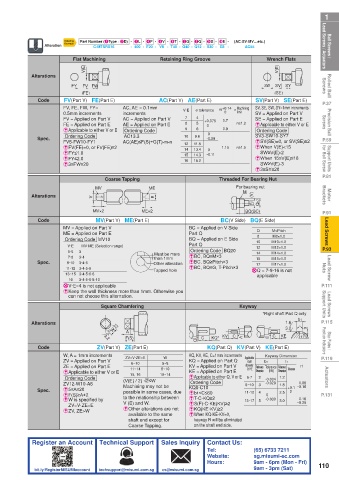
 Ball Screws /    Lead Screws / Actuators  Alteration  Ordering Flat Machining  - 400 - F20 - V8 - T40 - G40 - Q12 - S30 - E8 -  (AC·SV·MV…etc.)  Wrench Flats  Lead Screws / Actuators  Ball Screws /
                         Part Number (1Type · 2D) - 3L - 4F - 5V - 6T - 7G - 8Q - 9S - 0E -
                     Example
                                                                            AC55
                             C-MTSRX16
                                                  Retaining Ring Groove
                                                                                      V(E)
                           V(E)
 Rolled Ball   Screws  Alterations  FY  (FE)  FW                                 SW  (SE)  SY      Screws  Rolled Ball
                                                                                     SV
                          FV
                    FV(Part V)  FE(Part E)
                                                                               SV(Part V)  SE(Part E)
 P.37        Code   FV, FE, FW, FY=   AC, AE = 0.1mm  AC(Part V)  AE(Part E)  m +0.14  n     limit  SV, SE, SW, SY=1mm increments  P.37
                                                                         Machining
                                                             e tolerance
 Precision Ball   Screws  0.5mm increments  increments   7 8 9  4 5 6  +0.075  0.7  n≥1.2  SV = Applied on Part V  Screws  Precision Ball
                                                         V·E
                                                                     0
                    FV = Applied on Part V
                                                                               SE = Applied on Part E
                                      AC = Applied on Part V
                                                                               E  Applicable to either V or E
                                      AE = Applied on Part E
                    FE = Applied on Part E
                                                                 0
                                                                     0.9
                                       Ordering Code
                                                                               Ordering Code
                    E  Applicable to either V or E
                     Ordering Code
                                                            9.6
                                                                -0.09
 P.59       Spec.   FV5-FW10-FY1       AC13.3            10  11.5   0  1.15  n≥1.5  SV3-SW10-SY7   P.59
                                                                               ESV(SE)=0, or SV(SE)≥2
                                      AC(AE)≤F(S)+G(T)-m-n
                                                         12
 Support Units    for Ball Screw  EFY≤1.0                14  13.4   0 -0.11    E  When 15≤V(E)≤16   for Ball Screw  Support Units
                                                                               E  When V(E)<15
                    EFV(FE)=0, or FV(FE)≥2
                                                                                SW≥V(E)-2
                                                            14.3
                                                         15
                    EFY≤2.0
                                                            15.2
                                                         16
                                                                                SW≥V(E)-3
                    E3≤FW≤20
 P.81                                                                          E3≤SY≤20            P.81
                                 Coarse Tapping                     Threaded For Bearing Nut
 Motor   Brackets  Alterations  V  MV         ME E                       For bearing nut           Brackets  Motor
                                                                           M
                                                                              (V)
                                                                                Qh7
                                                                              Eh7
                                                                            BQ(BC)
 P.91        Code            MV×2           ME×2                    BC(V Side)  BQ(E Side)         P.91
 Lead Screws        MV = Applied on Part V                 BC = Applied on V Side   Q 8  M×Pitch    Lead Screws
                              MV(Part V)  ME(Part E)
                    ME = Applied on Part E
                                                           Part Q
                                                                                    M8×1.0
                     Ordering Code  MV10
                                                           BQ = Applied on E Side
                          MV·ME (Selection range)
                                                                                    M12×1.0
                                                                               12
 P.93                 V·E  3 3·4                Must be more   Part Q          10   M10×1.0        P.93
                                                           Ordering Code  BQ20
                      5·6
                                                                               14
                                                                                    M14×1.0
                                                           EBC, BQ≤M×3
 Lead Screw   Nuts  Spec.  13~15 3·4·5·6·8      Other alteration  EBC, BQ≥Pitch×3  X  Q = 7·9·16 is not   Nuts  Lead Screw
                      7·8
                                                than 1mm
                                                                               15
                                                                                    M15×1.0
                         3·4·5
                     9·10
                                                                               17
                                                                                    M17×1.0
                                                           EBC, BQ≤G, T-Pitch×3
                         3·4·5·6
                     11·12
                                                Tapped hole
                                                                               applicable
                      16
                         3·4·5·6·8·10
 P.111              XV·E=4 is not applicable                                                       P.111
                    E  Keep the wall thickness more than 1mm. Otherwise you
 Lead Screws   Support Units  can not choose this alternation.            Keyway                   Support Units  Lead Screws
                                Square Chamfering
                                                                                            b1
 P.115     Alterations             W -0.3                                        *Right shaft Part Q only t1  P.115
                                                                                        1.6
                                    -0.1
                                                                                        3.2
                                       A
 Stop Plates /    Position Indicators  Code  ZV(Part V)  ZE(Part E)  Q  C  KQ(Part Q)  KV(Part V)  KE(Part E)  r1  Position Indicators  Stop Plates /
                                                                                      KE
                                                                                    C
                                                                     KV
                                                                 KQ*
                                       F(S)
                                                                                   E
                                                                        C V
                                 3.2
 P.119              W, A = 1mm increments  ZV=V·ZE=E  W    KQ, KV, KE, C=1mm increments  Applicable    Keyway Dimension  P.119
                    ZV = Applied on Part V  6~10  5~8      KQ = Applied on Part Q  shaft   b1  t1
                    ZE = Applied on Part E  11~14  8~10    KV = Applied on Part V  diameter   Reference  Tolerance  Reference   Tolerance  r1
 Actuators          EApplicable to either V or E  (V(E) / 2) √2≤W  10~14  E  Applicable to either Q, V or E  8~10  2 3  -0.004  1.2  0.08  Actuators
                                                                             Q·V·E
                                                                                      Dimension
                                                                                    (N9)
                                                                               Dimension
                                                           KE = Applied on Part E
                                         15, 16
                     Ordering Code
                                                                            6·7
                                                           Ordering Code
                                                                                  -0.029
                    ZV12-W10-A8
                                                                                      1.8
                                       possible in some cases, due
                                                                                           0
                                                           Eb1<C≤60
                    EF(S)≥A+2
 P.131      Spec.   E5≤A≤20            Machining may not be   KQ8-C10       11·12  4  0  2.5  +0.1 ~0.16  P.131
                                       to the relationship between
                                                                                            0.16
                    E  W is specified by                   ET-C-KQ≥2        13~17  5  -0.030  3.0  ~0.25
                      ZV=V·ZE=E        V (E) and W.        ES(F)-C-KE(KV)≥2
                    EZV, ZE>W          E  Other alterations are not   EKQ(KE·KV)≥2
                                        available to the same   E  When KQ·KE·KV=0,
                                        shaft end except for   keyway R will be eliminated
                                        Coarse Tapping.     on the shaft end side.
           Register an Account  Technical Support  Sales Inquiry  Contact Us:
                                                                Tel:          (65) 6733 7211
                                                                Website:      sg.misumi-ec.com
                                                                Hours:        9am - 6pm (Mon - Fri)  110
            bit.ly/RegisterMISUMIaccount  techsupport@misumi.com.sg  cs@misumi.com.sg     9am - 3pm (Sat)
   110   111   112   113   114   115   116   117   118   119   120