Page 109 - MISUMI SINGAPORE Economy Series
P. 109

1                                                                                                  1


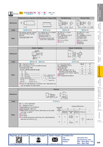
 Ball Screws /    Lead Screws / Actuators  Alteration No Retaining Ring Groove on Support Side End No Machining on Support Side  Flat Machining  Wrench Flats  Lead Screws / Actuators  Ball Screws /
                                             4S
                                       3L
                                                - (NAR…etc.)
                                           -
                         Part Number (1Type · 2D) -
                     Ordering
                     Example
                                           -
                                                    NAR
                                             S50
                                                -
                            C-MTSWK12
                                     -
                                        80
 Rolled Ball   Screws  Alterations  R  F                     FW    FE   FY     SY     SE    SW     Screws  Rolled Ball
                                                                                      E
                                                                    E
                                                                                   SE(Part E)
                        NAR(Part R)
                                            RC(Part R)
                                                               FE(Part E)
 P.37        Code   No machining of the support  No machining of the support  FE, FW, FY = 0.5mm   SE, SW, SY = 1mm   P.37
                                       side Part R steps.
                                                                              increments
 Precision Ball   Screws  Spec.  grooves.  E  Cannot be shared with   FE = Applied on Part E  SE = Applied on Part E  Screws  Precision Ball
                                                           increments
                    side Part R retaining ring
                                        Ordering Code  RC
                                                           Ordering Code
                                                                              Ordering Code
                     Ordering Code  NAR
                                                           FE5-FW10-FY1
                                                                              SE3-SW10-SY7
                                         other Part R alterations
                                                                              ESW≥E-2
                                                           EFY≤1.0
 P.59                                                      EFE=0, or FE≥2     ESE=0, or SE≥2       P.59
                                                                              E3≤SY≤20
 Support Units    for Ball Screw  MR  Coarse Tapping                  Square Chamfering            for Ball Screw  Support Units
                                    ME(MR)
 P.81      Alterations  R                 E  (D·R)                         A  3.2  W -0.1          P.81
                                  ME×2
 Motor   Brackets  Code     MR×2 ME(Part E)  MR(Left)                    ZE(Part E)  -0.3          Brackets  Motor
                                                                           S
                                  (MR×2)
                    ME = Applied on Part E                 A = 1mm increments     ZE=E    W
 P.91               MR = Machining in Part R and left end face  ZE = Applied on Part E  6  5       P.91
                                                           Ordering Code
 Lead Screws         E·R·D ME·MR (Selection range)         ZE12-W10-A8             10     9·10      Lead Screws
                     Ordering Code  ME6
                                                                                   8
                                                                                           6
                                                           E  Other alterations are not
                                                                                           8
                       6
                          3
                                                            available to the same shaft
                                                            end except for Coarse Tapping
                          3·4
                       8
                                                                                   12
                      10
                          3·4·5
                                                           EW is specified by ZE=E
 P.93       Spec.    14·15 3·4·5·6·8             Must be more   E5≤A≤20                            P.93
                                                 than 1mm
                      12
                          3·4·5·6
                                                 Other alteration
 Lead Screw   Nuts  E  Keep the wall thickness more than 1mm. Otherwise you                        Nuts  Lead Screw
                     16·18
                              5·6·8·10
                                                 Tapped hole
                     20~25
                              5·6·8·10·12
 P.111                can not choose this alternation.  Keyway                                     P.111
 Lead Screws   Support Units  Alterations                    1.6  b1  t1                           Support Units  Lead Screws
                                                             3.2
                                                         KE
 P.115       Code                                   E  C KE(Part E)  r1                            P.115
 Stop Plates /    Position Indicators  KE, C = 1mm increments            Keyway Dimension          Position Indicators  Stop Plates /
                    KE = Applied on Part E
                     Ordering Code   KE8-C10
                                                           shaft
 P.119              E  Applicable to D16 and above.       Applicable    b1      t1                 P.119
                    E  When KE=0, keyway R will be eliminated on the shaft   diameter    Reference   Tolerance  Reference    r1
                      end side, or KE≥2.                    E  Dimension   (N9)  Dimension  Tolerance
 Actuators  Spec.   Eb1<C≤60                               10     3   -0.004  1.8                   Actuators
                    ES-C-KE≥2
                    E  For additional keyway machining, the outside diameter
                                                                      -0.029
                                    0
                      tolerance of Part E is  -0.05 .                             +0.1  0.08~0.16
 P.131                                                                 0           0               P.131
                                                           12     4   -0.030  2.5
           Register an Account  Technical Support  Sales Inquiry  Contact Us:
                                                                Tel:          (65) 6733 7211
                                                                Website:      sg.misumi-ec.com
                                                                Hours:        9am - 6pm (Mon - Fri)  104
            bit.ly/RegisterMISUMIaccount  techsupport@misumi.com.sg  cs@misumi.com.sg     9am - 3pm (Sat)
   104   105   106   107   108   109   110   111   112   113   114