
Page 107 - MISUMI SINGAPORE Economy Series
P. 107
1 1
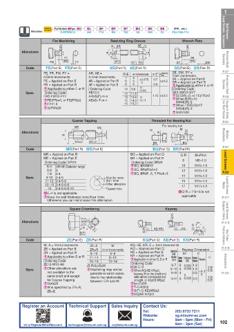
Ball Screws / Lead Screws / Actuators Alteration Ordering Flat Machining - 3L - - 4F - - Retaining Ring Groove - - 8S - - 9E - - FE2-FW8-FY1 Lead Screws / Actuators Ball Screws /
(FW…etc.)
6T
-
5R
-
7Q
Part Number (1Type · 2D) -
Example
C-MTSRK12
500
F10
R8
-
Q8
S20
-
E5
T20
Wrench Flats
AR
Rolled Ball Screws Alterations FW E(R) (FR) FY R n m e S(F) G(T) AE m e n E SY E(R) (SR) SW Screws Rolled Ball
SE
FE
F(S)
FE(Part E) FR(Part R)
SE(Part E) SR(Part R)
P.37 Code FE, FR, FW, FY = AR, AE = AR(Part R) AE(Part R) m 0 +0.14 n limit SE, SW, SY = P.37
Machining
R·E
e tolerance
1mm increments
Precision Ball Screws FE = Applied on Part E AR = Applied on Part R 10 9.6 +0.075 0.7 n≥1.2 SE = Applied on Part E Screws Precision Ball
0.5mm increments
0.1mm increments
4
7
5
8
SR = Applied on Part R
0
6
9
AE = Applied on Part E
0.9
FR = Applied on Part R
E Applicable to either E or R
0
Ordering Code
E Applicable to either E or R
Ordering Code
Ordering Code
ESE(SR)=0, or FE(FR)≥2
AR≤S(F)-m-n
P.59 Spec. FR5-FW10-FY1 AE13.3 12 11.5 -0.09 1.15 n≥1.5 SE3-SW10-SY7 P.59
14
0
13.4
E When E(R)<15
AE≤S+T-m-n
EFE(FR)=0, or FE(FR)≥2
-0.11
15
14.3
Support Units for Ball Screw E FY≤1.0 16 15.2 E When 15≤E(R)≤17 for Ball Screw Support Units
SW≥E(R)-2
E3≤FW≤20
SW≥E(R)-3
E 3≤SY≤20
P.81 Coarse Tapping Threaded For Bearing Nut P.81
MR ME M For bearing nut M
Motor Brackets Alterations R E R Eh7 Qh7(V) Brackets Motor
MR×2
ME×2
P.91 Code MR(Part R) ME(Part E) BR BQ P.91
BQ(Part Q) BR(Part R)
Lead Screws MR = Applied on Part R BQ = Applied on Part Q Q·R M10×1.0 Lead Screws
M×Pitch
ME = Applied on Part E
BR = Applied on Part R
M8×1.0
8
Ordering Code BR20
Ordering Code MR10
10
EBQ, BR≤M×3
MR·ME (Selection range)
R·E
5·6
P.93 Spec. 9·10 3 3·4 Must be more EBQ, BR≥Pitch×3 12 M12×1.0 P.93
EBQ, BR≤F, S, T-Pitch×3
7·8
14
M14×1.0
Lead Screw Nuts 13~15 3·4·5·6·8 Other alteration 15 M15×1.0 Nuts Lead Screw
3·4·5
than 1mm
11·12 3·4·5·6
17
M17×1.0
3·4·5·6·8·10
16
Tapped hole
applicable
E Keep the wall thickness more than 1mm.
P.111 X E=4 is not applicable X Q·R = 7·9·16 is not P.111
Otherwise you can not choose this alternation.
Lead Screws Support Units Square Chamfering Keyway Support Units Lead Screws
P.115 Alterations A 3.2 W -0.1 C KE(KR) Q(V) C KQ 1.6 3.2 b1 t1 P.115
E(R)
Stop Plates / Position Indicators Code ZE(Part E) ZR(Part R) KQ(Part Q) KE(Part E) KR(Part R) r1 Position Indicators Stop Plates /
-0.3
S(F)
W
P.119 W, A = 1mm increments ZE=E 1mm increments KQ, KE, KR, C = 1mm increments Keyway Dimension P.119
ZE = Applied on Part E
KQ = Applied on Part Q
ZR=R
ZR = Applied on Part R 6~10 5~8 KE = Applied on Part E Applicable b1 t1
shaft
KR = Applied on Part R
Actuators ZE12-W10-A8 (E·R/2)√2≤W 10~14 E Applicable to either Q, E or R diameter Reference Tolerance Reference Tolerance r1 Actuators
E Applicable to either E or R
8~10
11~14
Q·E·R
Ordering Code
Dimension
(N9)
Dimension
15~16
Ordering Code
6·7 2 -0.004 1.2
0.08
E When KQ(KE·KR)=0,
not available to the
11·12 4
2.5
P.131 Spec. E Other alterations are E Machining may not be KQ8-C10 8~10 3 -0.029 1.8 +0.1 ~0.16 P.131
possible in some cases,
keyway R on the shaft end
0
same shaft end except due to the relationship side will be eliminated and 0 0.16
for Coarse Tapping between E/R and W. straight, or KQ(KE·KR)≥2 13~17 5 -0.030 3.0 ~0.25
E5≤A≤20 Eb1<C≤60
E W is specified by ZR=R, ET-C-KQ≥2
ZE=E ES(F)-C-KE(KR)≥2
EKQ(KE·KR)≥2
Register an Account Technical Support Sales Inquiry Contact Us:
Tel: (65) 6733 7211
Website: sg.misumi-ec.com
Hours: 9am - 6pm (Mon - Fri) 102
bit.ly/RegisterMISUMIaccount techsupport@misumi.com.sg cs@misumi.com.sg 9am - 3pm (Sat)