
Page 105 - MISUMI SINGAPORE Economy Series
P. 105
1 1
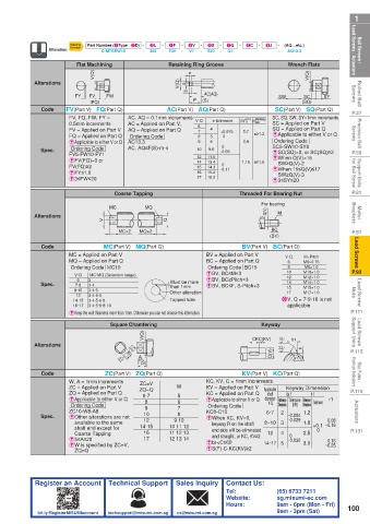
Ball Screws / Lead Screws / Actuators Alteration Ordering Part Number (1Type · 2D) - - 3L - - Retaining Ring Groove 7Q - 8C - 9J - - (AQ…etc.) Lead Screws / Actuators Ball Screws /
-
4F
6S
-
5V
-
Example
-
S20
Q7
-
V7
300
C-MTSRW10
-
F20
AQ13.3
Wrench Flats
Flat Machining
V(Q)
Rolled Ball Screws Alterations FY FV V(Q) FW V(Q) m e n F (S) SW (SQ) SY Screws Rolled Ball
AC(AQ)
SC
(FQ)
AC(Part V) AQ(Part Q)
SC(Part V) SQ(Part Q)
P.37 Code FV(Part V) FQ(Part Q) AC, AQ = 0.1mm increments V·Q e tolerance m 0 +0.14 n limit SC, SQ, SW, SY=1mm increments P.37
FV, FQ, FW, FY =
Machining
Precision Ball Screws 0.5mm increments AC = Applied on Part V, 6 7 8 9 4 5 6 +0.075 0.7 n≥1.2 SQ = Applied on Part Q Screws Precision Ball
SC = Applied on Part V
FV = Applied on Part V
AQ = Applied on Part Q
E Applicable to either V or Q
FQ = Applied on Part Q
Ordering Code
0
Ordering Code
AC13.3
0.9
EApplicable to either V or Q
Ordering Code
9.6
ESC(SQ)=0, or SC(SQ)≥2
P.59 Spec. FV5-FW10-FY1 AC, AQ≤F(S)-m-n 10 11.5 0 1.15 n≥1.5 SC5-SW10-SY8 P.59
-0.09
12
E When Q(V)<15
Support Units for Ball Screw FV(FQ)≥2 15 14.3 0 E When 15≤Q(V)≤17 for Ball Screw Support Units
EFV(FQ)=0 or
13.4
14
SW≥Q(V)-2
-0.11
EFY≤1.0
16
15.2
SW≥Q(V)-3
16.2
17
E3≤FW≤20
E3≤SY≤20
P.81 Coarse Tapping Threaded For Bearing Nut P.81
Motor Brackets Alterations V MC MQ Q For bearing nut Brackets Motor
Q(V)
M
BC
P.91 MC×2 MQ×2 (BV) P.91
Lead Screws Code MC = Applied on Part V BV = Applied on Part V V·Q M6×0.75 Lead Screws
BV(Part V) BC(Part Q)
MC(Part V) MQ(Part Q)
M×Pitch
BC = Applied on Part Q
MQ = Applied on Part Q
6
Ordering Code BC15
M8×1.0
8
P.93 Ordering Code MC10 Must be more EBV, BC≤M×3 10 M10×1.0 P.93
MC·MQ (Selection range)
V·Q
M12×1.0
12
EBV, BC≥Pitch×3
6
3
Lead Screw Nuts Spec. 14·15 3·4 Other alteration EBV, BC≤F, S-Pitch×3 X V, Q = 7·9·16 is not Nuts Lead Screw
M14×1.0
14
7·8
than 1mm
M15×1.0
15
9·10
3·4·5
M17×1.0
17
12
3·4·5·6
Tapped hole
3·4·5·6·8
3·4·5·6·8·10
16·17
P.111 E Keep the wall thickness more than 1mm. Otherwise you can not choose this alternation. applicable P.111
Lead Screws Support Units Square Chamfering CKC(KV) 1.6 b1 Support Units Lead Screws
Keyway
V(Q)
-0.1
P.115 Alterations 3.2 #W -0.3 A Q(V) 3.2 r1 t1 P.115
F(S)
Stop Plates / Position Indicators Code ZC(Part V) ZQ(Part Q) KC, KV, C = 1mm increments Position Indicators Stop Plates /
KV(Part V) KC(Part Q)
ZC=V
ZC = Applied on Part V
P.119 W, A = 1mm increments ZQ=Q W KV = Applied on Part V Applicable Keyway Dimension P.119
ZQ = Applied on Part Q
KC = Applied on Part Q
b1
t1
shaft
EApplicable to either V or Q 6·7 5 6 E Applicable to either V or Q diameter Reference Tolerance Reference Tolerance r1
8
V·Q
Actuators Spec. ZC10-W8-A8 10 9 10 KC8-C10 6·7 2 -0.004 1.2 0.08 Actuators
Dimension
Dimension
(N9)
Ordering Code
Ordering Code
9
7
8
E Other alterations are not
E When KC, KV=0,
12
-0.029
shaft end except for
end side will be eliminated
0
P.131 available to the same 14·15 10 11 12 keyway R on the shaft 8~10 3 4 1.8 +0.1 ~0.16 P.131
16
11 12 13
12
2.5
Coarse Tapping
and straight, or KC, KV≥2
E5≤A≤20 17 12 13 14 Eb1<C≤60 0 0.16
-0.030
E W is specified by ZC=V, 14~17 5 3.0 ~0.25
ZQ=Q ES(F)-C-KC(KV)≥2
Register an Account Technical Support Sales Inquiry Contact Us:
Tel: (65) 6733 7211
Website: sg.misumi-ec.com
Hours: 9am - 6pm (Mon - Fri) 100
bit.ly/RegisterMISUMIaccount techsupport@misumi.com.sg cs@misumi.com.sg 9am - 3pm (Sat)