
Page 101 - MISUMI SINGAPORE Economy Series
P. 101
1 Economy series Product Overview Product Specifications Economy series 1
Lead Screws
Lead Screws
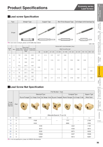
Ball Screws / Lead Screws / Actuators QEasy Assembly Design QLead screw Specification Lead Screws / Actuators Ball Screws /
Rolled Ball Screws Step 1 Select the lead screw rotating unit Step 2 Select components. Type Straight Type Support Type Both Ends Stepped Type One End Stepped / One End Double Stepped Type Screws Rolled Ball
drawing that meets the conditions of use.
1. Please determine the lead screw shaft diameter D, dimensions L
and S according to the conditions of use.
· Square type stop plate for
2. Please select components from the specification correspondence table
installation of position indicator
based on the lead screw shaft diameter D determined in step 1.
P.37 Lead screw rotating unit Shape P.37
Precision Ball Screws Screws Precision Ball
P.59 d 5 3 EFor more shaft end shapes, please visit MISUMI official website. Unit: mm P.59
Support Units for Ball Screw · Round type stop plate for Exploded view D Shaft Pitch Effective Dia. diameter Lead Angle Screw shaft runout tolerance (max.) for Ball Screw Support Units
installation of position indicator
Screw shaft
Screw Shaft thread root Screw Shaft
Shaft Overall Length
Dia.
4
P.81 6 2 1 S L 8 1.5 7.25 (MIN) 3°46' ~125 126~200 201~315 316~400 401~500 501~630 631~800 801~1000 1001~1200 P.81
(5.9)
-
0.27
0.21
0.14
-
-
0.1
0.35
Motor Brackets 10 2 11 (7.2) 4°03' 0.09 0.12 0.16 0.21 0.27 0.35 0.46 0.58 - Brackets Motor
9
12
3°19'
(9.2)
P.91 QExample of Use 14 3 12.5 (10.1) 4°22' 0.09 - P.91
Lead Screws The structure combines the lead screw support unit, the stop plate, the special lead screw shaft and the position indicator. 16 4 14.5 (12.1) 3°46' - 0.11 0.13 0.16 0.2 0.25 0.32 0.42 0.55 Lead Screws
Machine name: Roll bracket with adjustment mechanism
18
20
4°03'
(15.1)
P.93 IIntended Use 22 5 19.5 (16.1) 4°40' - 0.09 0.11 0.13 0.16 0.19 0.23 0.3 0.38 P.93
Regularly detects the outside diameter margin of steel rolls and raises the
Lead Screw Nuts steel roll core by the lead screw.The feed rate of the lead screw is confirmed 25 22.5 (19) 4°03' Nuts Lead Screw
by the position indicator instead of the conversion table.
ISelection Points
+
Lead Screw Nut
P.111 Lead Screw Support Unit Type Lead Screw Support 1 Lead Screw Support Unit Type QLead Screw Nut Specification P.111
Stop Plates
The special lead screw shaft for the
Lead Screws Support Units 2 3 as the support side without R Standard Type Part Number / Type Compact Type Square Type Support Units Lead Screws
lead screw support unit is selected
machining (RC alteration) type.
Lead Screw Support Unit
P.115 A combination of the fixed Round Flanged Cut Flange 2-hole Cut Flange 4-hole Square Flanged Round Flanged Cut Flange 2-hole Wide Block P.115
side support containing the
support side and stop plate is
Stop Plates / Position Indicators Steel Inlet A Part Detail Position Indicator 4 selected. Diameter Pitch Position Indicators Stop Plates /
Thread
Nominal
The small position indicator
P.119 can be mounted directly. P.119
5 Lead Screw Nut
Actuators Steel Roll Select the compact type to Allowable Dynamic Thrust (N) Actuators
save space.
PBR 8 1.5 1250 — — —
P.131 6 10 2 2168 — 1717 — 2168 P.131
Position Indicator 12 2 3332 2669 3332
A Part It is convenient to confirm the 14 3 4165 3332 4165
feed rate of the lead screw.
16 3 5670 4539 5670
IOperating Condition 20 4 8339 6673 8339
22 5 10506 8407 10506
Loading weight 20kN
25 5 12087 9673 12087
Positioning accuracy 1~2mm
EFor more nut specifications, please visit MISUMI official website.
Stroke 150mm
96