Page 141 - MISUMI SINGAPORE Economy Series
P. 141

1                                                                                                  1


 Ball Screws /    Lead Screws / Actuators  1Type  Lead  Block  Base Length L2  Motor Bracket   Sensors  Length L1  Block Qty.   Block Qty.   (mm)  n Block Qty.  Block Qty.   Lead Screws / Actuators  Ball Screws /
             Part Number
                                                                                      Weight (kg)
                                                               Maximum Stroke
                                  4
                                                           Total
                           3
                                           5
                                                     6
                                                                             G
                     2
                                                    Qty.
                                                           (mm)
                                       and Attachments
                                 (mm)
                          Qty.
                                                                                     1 pcs
                                                                       2 pcs
                                                                1 pcs
                                                                                           2 pcs
                                                                                            -
                                                                 70
                                                                        -
          C-KS50
                                                    (None)
                                        Motor Bracket
                                                  W1(1 pcs.)
          (Standard       B1     150   Bracket and Attachment  Leave Blank   220  120  55  35  2 3  1.1  1.4
                                           F0
                                                  W2(2 pcs.)
 Rolled Ball   Screws  02  (1 pcs.)  250   F1     W3(3 pcs.)  320  170  105  45  3   1.4    1.6    Screws  Rolled Ball
          Type)
                                                           270
                                                                             20
                                 200
                                                                                     1.2
                                           F2
                          B2
                     10
                                                  Leave Blank
                                           F3
                         (2 pcs.)
                                                    (None)
                                           H0
          (Cover Type)
                                                  CW2(2 pcs.)
 P.37     C-KSC50                300   Without Motor Bracket   CW1(1 pcs.)   370  220  155  30  4  1.6  1.8  P.37
                                                  CW3(3 pcs.)
 Precision Ball   Screws  E 2 blocks is not applicable to base length 150.                         Screws  Precision Ball
          EFor detailed dimensions, please refer to the website.
                  Please order after selecting part number and parameters according to the selection steps 1 to 6.
          Ordering
                  Part Number (1Type · 2Lead) - 3Block Qty. - 4Base Length - 5Motor Bracket and Attachments - 6Sensor Qty.
          Example
 P.59     Motor Bracket F0  C-KSC5002  -   B1     -    150     -          F0         -    CW1      P.59
 Support Units    for Ball Screw  Motor Bracket F0  4-M3 Depth 8                                   for Ball Screw  Support Units
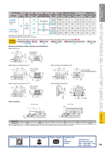
          Dimensional Drawing of Motor Brackets and Attachments
          Motor Bracket F0
                 60
                 60
            14
                  34
                              4-M3 Depth 8
                 60
                               P.C.D. 33
            14
                  34
                               P.C.D. 33
                 17
                               P.C.D. 33
                 17
 P.81       14  8 8 8  17 34  φ 5h75h7  φ 5h7  φ  φ 24 +0.03+0.03  φ 24 +0.03  φ 24  0.03.03  0  0.03  4-M3 Depth 8  45° 45°  45°  P.81
                              38.5 38.5
                              38.5
 Motor   Brackets               1616  16  0.5  0.5  45° 45° 45°                                    Brackets  Motor
          Motor Bracket and Attachment F1  0.5     Motor Bracket and Attachment F3
 P.91     Motor Bracket and Attachment F1 4-M4 Through  Motor Bracket and Attachment F3  49.4  4- φ 3.5 Through  P.91
                                                   Motor Bracket and Attachment F3
          Motor Bracket and Attachment F1
                      8.5
                 60
                                                           60
                                                               7
                      8.5
                                                           60
                                                               7
 Lead Screws  14  8 8 8  17 60  8.5  3.2 +0.05 0.05 +0.05 +0.05  φ 3030  0.05  0.05  P.C.D. 46  45°  14  8 8 8  17 60  7  φ 5h75h7  φ 5h7  φ  φ 22 +0.05+0.05  φ 22 +0.05  φ 22  +0.05+0.05  +0.05  4040  49.4  4- φ 3.5 Through  Lead Screws
                                                           34
                                                     14
                 60
                                                                           49.4
                         3.2
                  34
                              4-M4 Through
            14
                                                                            31
                              4-M4 Through
                                                           34
                  34
                                                                                 φ 6 Counterbored Depth3.5
                                                                            31
                                                           34
                                                     14
                              P.C.D. 46
            14
                         3.2
                                                                                 4- φ 3.5 Through
                  34
                                                                            31
                                                                                 φ 6 Counterbored Depth3.5
                              P.C.D. 46
                                                          17
                         φ 5h75h7
                 17
                                                                                 φ 6 Counterbored Depth3.5
                 17
                                                          17
                         φ 5h7
                         φ
                                           45°
 P.93                      φ 30 φ  38.5 38.5  38.5  1616  16  0.5  0.5  #40  45° 45° 45°  45°  40  49  15.5 15.5  15.5  3131  31  P.93
                                                                            49
 Lead Screw   Nuts  Motor Bracket and Attachment F2  0.5  #40  Without Motor Bracket H0  49.4      Nuts  Lead Screw
                                                                            49
                                    #40
                                                   Without Motor Bracket H0
          Motor Bracket and Attachment F2
                                                   Without Motor Bracket H0
                                                         14 9
          Motor Bracket and Attachment F2 4-M3 Through
                                                                             49.4
                                                         14 9
                     8.5 3.2
                 60
                 34
                                                         14 9 8
                                                                             49.4
                               P.C.D. 45
                                                         11
                              4-M3 Through
                     8.5
 P.111      14  8  17 60  8.5  3.2  0.05.05 0.05  0  4-M3 Through  45°  11  8 8  φ 25 φ 25  φ 25  4-M3 Depth 8  R3  P.111
                                                                            4-M3 Depth 8
                 60
                 34
            14
                                                         11
                               P.C.D. 45
                        3.2 +0.05
                                                                            4-M3 Depth 8 R3
                 34
            14
                               P.C.D. 45
                17
 Lead Screws   Support Units  8 8  17  φ 5h75h7  φ 5h7  φ  φ 30 +0.05  φ 30  φ 30 +0.05  38.5 38.5  38.5  1616  16  0.5  #40  45° 45°  45°  45°  35.5 35.5  35.5  2424  24  32  R3 17.5 17.5  17.5  Support Units  Lead Screws
                                          45°
                                                                             32
                                                                             32
                                    #40
                                                                             36.5
                                                                                    6.45
 P.115                            0.5  0.5  #40                φ 5H75H7  φ 5H7  φ  36.5  6.45      P.115
                                                                                    6.45
                                                                             36.5
          Sensor Drawing
 Stop Plates /    Position Indicators  Standard Type  b  e      e  Cover Type                      Position Indicators  Stop Plates /
                                  b
 P.119                             a        a                                                      P.119
 Actuators              d  c     d  c             f        f                                        Actuators
            Dimension       a           b           c           d            e           f
 P.131       50 Series     44.5        59.8         -           12          14          11.55      P.131
          Note: The applicable sensor is L-Shape Photo Microsensors with NPN Type “C-MSX671N-2M”. For detail please refer to P.903.
           Register an Account  Technical Support  Sales Inquiry  Contact Us:
                                                                Tel:          (65) 6733 7211
                                                                Website:      sg.misumi-ec.com
                                                                Hours:        9am - 6pm (Mon - Fri)  136
            bit.ly/RegisterMISUMIaccount  techsupport@misumi.com.sg  cs@misumi.com.sg     9am - 3pm (Sat)
   136   137   138   139   140   141   142   143   144   145   146