
Page 343 - MISUMI SINGAPORE Economy Series
P. 343
Economy Series Product Overview Product Overview Economy Series
Cross Roller Guides Cross Roller Guides
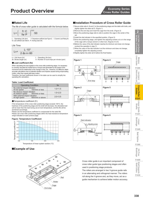
QRated Life QInstallation Procedure of Cross Roller Guide
vs Standard Type
Economy Series New Saving The life of cross roller guide is calculated with the formula below. 1 Secure slide rails A, B and C to the positioning stage and the table with bolts, and
slightly tighten the slide rail D. (Figure 1)
)
(
up to
fT·C
10/3
2 Cross Roller Guides Products 80 % L= ·50 2 Remove the end stop and insert the cage from the ends. (Figure 2) 2
3 Move the positioning stage side to side to position the cage in the center of the
fw·P
rail.
Linear Guides / Linear Bushings / Ball Splines / Oil Free Bushings High rigidity L : Operating Life (km) fT: Temperature coefficient (see Figure-2) C: Dynamic Load Rating (N) 5 Drive the positioning stage, and tighten the adjusting screws a to e in the range Ball Splines / Oil Free Bushings Linear Guides / Linear Bushings /
4Install the dial indicator in the specified position. (Figure 3)
fw: Load coefficient (see Table-4) P: Acting load (N)
of the cage with a torque wrench or other tool. (Figures 4 to 6)
6 Before the value of the dial indicator reaches its minimum and does not change,
Life Time
conduct the operation in step 5.
7 When the value of the dial indicator is at the minimum and does not change,
L·10
3
completely tighten the adjusting screws.
2·Ls·n1·60
Smooth movement Lh= 8Slightly tighten the slide rail D before the final fixation.
Miniature Linear Guides Rich in specifications Lh: Life Hours (hr) L : Operating Life (km) Figure 1 Figure 4 Cage Linear Guides Miniature
Ls: Stroke length (m)
n1: Number of round trips per minute (cpm)
I Load coefficient (fW)
to correctly calculate the inertial force or torque load generated by the speed of the
P.309 When calculating the load applied on the cross roller positioning stage, it is necessary B C P.309
movement and its relationship to the change in time, etc.. However, it is difficult to attain
accurate calculations due to potential vibration and impacts caused during reciprocating
Linear Guides for Medium and Heavy Load motion, other than repeat start-stop motion. A D Medium and Heavy Load Linear Guides for
Therefore, the load coefficients shown in the table can be used to simplify the
operating life calculation.
P.321 Table: Load Coefficient fw End stop a b c d e P.321
Operating Condition
Cross Roller Guides No external impact vibration 1.0~1.5 Figure 2 Cage Figure 5 Guides Cross Roller
At low speed 15m/min or less
No obvious impact vibration
1.5~2.0
At medium speed 60m/min or less
With external impact vibration
At high speed 60m/min or above
P.337 ITemperature coefficient (fT) 2.0~3.5 P.337
Linear Guide Shafts If the temperature of the cross roller positioning stage exceeds 100°C, the a b c d e Shafts Linear Guide
hardness of the positioning stage and the shaft will decrease, the allowable load
will be lower than the load during use at room temperature, and the life will be
shortened accordingly.
P.341 Please use the temperature coefficient to compensate for the rated life. P.341
Please use cross roller positioning stages within the heat-resistance temperature
range indicated on each product page. Figure 3 Figure 6
Linear Bushings Figure: Temperature Coefficient Dial indicator Bushings Linear
1.0
Adjusting screw
0.9
P.349 Temperature coefficient fT 0.8 Adjustment P.349
0.7
Ball Spline 0.6 Side a b c d e Ball Spline
0.5
100
150
Temperature of linear system section (°C)
P.386 QExample of Use 200 250 P.386
Oil Free Bushings Bushings Oil Free
P.409 Cross roller guide is an important component of P.409
Shaft Supports Shaft Collars Rail cross roller guide type positioning stages and often Shaft Collars Shaft Supports
used in positioning stage products.
The rollers are arranged in two V-groove guide rails
P.430 in an alternating and orthogonal manner. The rollers P.430
roll along the V-groove and, as they move, act as a
Rail
guide mechanism to achieve better motion accuracy.
Roller
Cage
End stop
338