Page 295 - MISUMI SINGAPORE Economy Series
P. 295

1                                                                                                  1


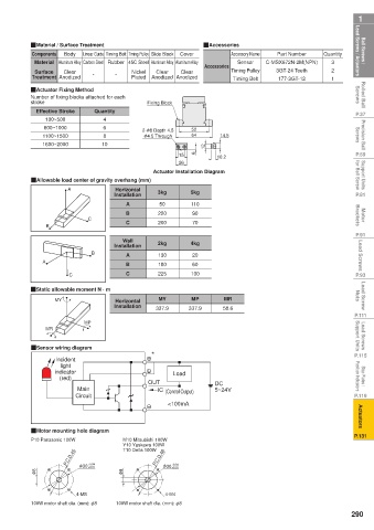
 Ball Screws /    Lead Screws / Actuators  QMaterial / Surface Treatment  Nickel   Clear   Cover  QAccessories Sensor  C-MSX672N-2M(NPN)  Quantity  Lead Screws / Actuators  Ball Screws /

                                                                 Accessory Name
                                                                             Part Number
                   Body
                        Linear Guide Timing Belt Timing Pulley Slide Block
          Components
           Material Aluminum Alloy Carbon Steel Rubber 45C Steel Aluminum Alloy Aluminum Alloy
                                                                                            3
                                                         Accessories
                                                                             3GT-24 Teeth
                                                                 Timing Pulley
                                                                                            2
           Surface
                   Clear
                                                   Clear
                                           Anodized Anodized
          Treatment Anodized
 Rolled Ball   Screws  QActuator Fixing Method -  -  Plated  Fixing Block  Timing Belt  177-3GT-12  1  Screws  Rolled Ball
          Number of fixing blocks attached for each
          stroke
 P.37      Effective Stroke  Quantity                                                              P.37
              100~500
                              4
 Precision Ball   Screws  1100~1500  10  2- φ 8 Depth 4.5  52  14.5                                Screws  Precision Ball
                              6
             600~1000
                                                      64
                              8
                                         φ 4.5 Through
             1600~2000
 P.59                                             15   6  12  10.2                                 P.59
 Support Units    for Ball Screw  QAllowable load center of gravity overhang (mm)  Actuator Installation Diagram  for Ball Screw  Support Units
                                                  26
                                 Horizontal
 P.81               A            Installation  3kg    5kg                                          P.81
                                    A        50       110
 Motor   Brackets        C          B        220      90                                           Brackets  Motor
                                    C
                                                      70
                                             200
 P.91         B                    Wall      2kg      4kg                                          P.91
 Lead Screws  A           B      Installation  130    20                                            Lead Screws
                                    A
                                             180
                                                      60
                                    B
 P.93               C               C        225      100                                          P.93
 Lead Screw   Nuts  QStatic allowable moment N · m  Horizontal   MY  MP  MR                        Nuts  Lead Screw
                MY
 P.111                  MP       Installation  337.9  337.9    58.6                                P.111
 Lead Screws   Support Units  MR                                                                   Support Units  Lead Screws
 P.115    QSensor wiring diagram           *                                                       P.115
                Incident
                  light
 Stop Plates /    Position Indicators  indicator   OUT  Load  DC                                   Position Indicators  Stop Plates /
                 (red)
                      Main
 P.119                Circuit               IC  (Control Output)  5~24V                            P.119
                                               <100mA
 Actuators                                                                                          Actuators


 P.131    QMotor mounting hole diagram                                                             P.131
          P10 Panasonic 100W       M10 Mitsubishi 100W
                                   Y10 Yaskawa 100W
                                   T10 Delta 100W
                   P.C.D.45  +0.04          P.C.D.46
                                                +0.01
           φ 8         φ 30  +0.01  φ 8       φ 30 +0.04

                      4-M3                     4-M4
          100W motor shaft dia. (mm): φ8  100W motor shaft dia. (mm): φ8
                                                                                                  290
   290   291   292   293   294   295   296   297   298   299   300