
Page 243 - MISUMI SINGAPORE Economy Series
P. 243
1 1
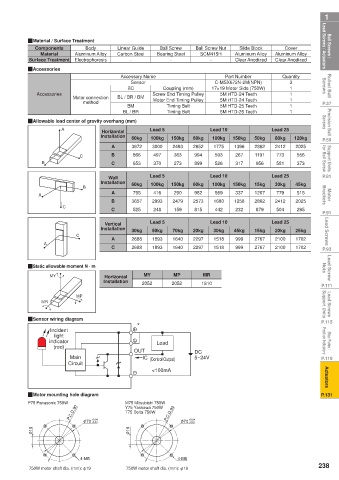
Ball Screws / Lead Screws / Actuators QMaterial / Surface Treatment Carbon Steel Bearing Steel Ball Screw Nut Aluminum Alloy Aluminum Alloy Lead Screws / Actuators Ball Screws /
Linear Guide
Ball Screw
Components
Cover
Slide Block
Body
Aluminum Alloy
Material
SCM415H
-
Clear Anodized
Clear Anodized
Electrophoresis
-
-
Surface Treatment
Rolled Ball Screws QAccessories Accessory Name Coupling (mm) 17×19 Motor Side (750W) Quantity Screws Rolled Ball
Part Number
3
Sensor
C-MSX672N-2M(NPN)
BC
1
Screw End Timing Pulley
5M HTD-24 Teeth
1
Accessories
method
P.37 Motor connection BL / BR / BM Motor End Timing Pulley 5M HTD-24 Teeth 1 1 1 P.37
Timing Belt
5M HTD-25 Teeth
BM
Precision Ball Screws QAllowable load center of gravity overhang (mm) Lead 5 Lead 10 Lead 25 Screws Precision Ball
5M HTD-25 Teeth
BL / BR
Timing Belt
A
Horizontal
P.59 Installation 60kg 100kg 150kg 60kg 100kg 150kg 50kg 80kg 120kg P.59
2025
2493
Support Units for Ball Screw B C B 866 497 363 994 593 267 1191 773 556 for Ball Screw Support Units
3000
3672
1396
2862
1775
2652
2412
A
899
370
653
273
C
581
373
956
526
317
P.81 Wall Lead 5 Lead 10 Lead 25 P.81
Installation 60kg 100kg 150kg 60kg 100kg 150kg 15kg 30kg 45kg
B
Motor Brackets A A 3657 2993 2479 2573 1680 1258 1207 2412 2025 Brackets Motor
337
779
290
982
569
515
416
795
2862
B
C C 525 248 159 815 442 232 879 504 295
P.91 Lead 5 Lead 10 Lead 25 P.91
Lead Screws C Installation 30kg 50kg 70kg 20kg 30kg 45kg 15kg 20kg 25kg Lead Screws
Vertical
2767
1518
2100
2688
1702
1640
1893
999
A
2297
P.93 A C 2688 1893 1640 2297 1518 999 2767 2100 1702 P.93
Lead Screw Nuts QStatic allowable moment N · m MY MP MR Nuts Lead Screw
MY
Horizontal
P.111 Installation 2052 2052 1810 P.111
Lead Screws Support Units MR MP Support Units Lead Screws
P.115 QSensor wiring diagram * P.115
Incident
Stop Plates / Position Indicators indicator Load Position Indicators Stop Plates /
light
(red)
5~24V
P.119 Main OUT IC (Control Output) DC P.119
Circuit <100mA
Actuators Actuators
P.131 QMotor mounting hole diagram P.131
P75 Panasonic 750W M75 Mitsubishi 750W
P.C.D.90 Y75 Yaskawa 750W P.C.D.90
T75 Delta 750W
+0.04
+0.04
φ 70 +0.01 φ 70 +0.01
φ 19 φ 19
4-M5 4-M6
238
750W motor shaft dia. (mm): φ19 750W motor shaft dia. (mm): φ19