
Page 149 - MISUMI SINGAPORE Economy Series
P. 149
1 1
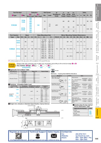
Ball Screws / Lead Screws / Actuators 1Type 2No. Base Length Table Length Dia. Lead Workbench Total Guide Axis L1 t2 Table P1 P2 Lead Screws / Actuators Ball Screws /
Selection
Ball Screw
Part Number
H1
H
H2
W
3L*
4L1
M1
Height Height Height
Width
340
460
1520L
Rolled Ball Screws E-KUA 1510L 400 150 15 10 200 64 28 32 150 12 M6 80 160 Screws Rolled Ball
520
580
20
640
79
40
39
2010L
760
P.37 2020L 700 20 68 28 34 100 150 P.37
820
Precision Ball Screws Part Number W1 H4 Base t1 h1 P3 Base Mounting Hole S P.C.D D Motor Mounting Related Dimensions M2 R Screws Precision Ball
Q
No.
N
Type
h
d
N2
N3
N1
D1
H3
S
L
L
Q
P.59 1510L 49 20 340 6 340 50 62 45 40 15 10 P.59
1520L
Support Units for Ball Screw E-KUA 2010L 195 61 12 29 120 11.5 460 8 460 50 70 50 45 70 57.5 5 12 M5 10 for Ball Screw Support Units
400 8
400 20
520 20
520 10
640 20
640 12
P.81 580 10 580 50 39.5 20 P.81
700 12 700 50
760 14
760 20
Motor Brackets 2020L 55 20 820 14 820 50 64 57.5 12 Brackets Motor
P.91 E*L=340 is suitable for 1510L only, and L=400 is suitable for 1510L and 2010L only. P.91
Please order after selecting part number and parameters according to the selection steps 1 to 4.
Ordering
-
3L
Part Number (1Type · 2No.) -
Lead Screws QApplicable Servo Motor Table Output (W) - 340 - 150 Alteration Lead Screws
4L1
Example
E-KUA1510L
Square Flange
Part Number
Manufacturers
400
SGM7J-04
P.93 Yaskawa Electric SGM7J-02 200 Ball Screw Coupling Side Shaft End Alterations Spec. P.93
HG-MR23
200
Code
Alterations
200
HG-KR23
Lead Screw Nuts Mitsubishi Electric HG-MR43 200 #60 shaft end keyways KC KC Adds keyways. Part Number 3≤KC≤14 Nuts Lead Screw
Machining fixed side
200
HF-MP23
HF-KP23
KC
400
KC = 1mm increments
E-KUA15
400
HG-KR43
Ordering Code
4≤KC≤19
E-KUA20
400
HF-MP43
KC10
HF-KP43
K·S
P.111 QPrecision · Allowable Static Load 400 Machining fixed side The machining Part Number 3≤K≤14 P.111
position of keyways
shaft end keyways
Part Number No. Repeatability (mm) Horizontal Vertical *Parallelism K S KLC can be specified. E-KUA15 4≤K+S≤14
*Positioning
Allowable Static Load (kg)
K, S = 1mm increments
Lead Screws Support Units 1510L 2897 153 340 Parallelism Machining fixed side SC KLC-K5-S2 Part Number 5≤K+S≤19 Support Units Lead Screws
(mm)
Type
4≤K≤19
E-KUA20
Ordering Code
L
0.06
Adds planes.
SC
400
0.07
shaft end plane
SC = 1mm increments
0.08
460
E-KUA15
5≤SC≤14
Ordering Code
Screws
P.115 Rolled Ball 1520L ±0.05 520 0.09 SC 0.5 SC7 E-KUA20 5≤SC≤19 P.115
0.10
580
E-KUA
2010L 4345 169 640 0.12 Machining a plane at Adds planes at 2 Part Number SWC
fixed side shaft end
0.13
700
places (90° position).
Stop Plates / Position Indicators QSingle Axis Actuators Standard Specification Optical Sensor (2 places) SWC 0.5 0.5 SWC SWC = 1mm increments E-KUA15 5≤SWC≤14 Position Indicators Stop Plates /
760
0.14
2020L
Ordering Code
0.15
820
5≤SWC≤19
E-KUA20
SWC7
Sensor Dimensions Table
P.119 2-φ4.5 Through 28 Q Standard Specification Optical P.119
2.3 20 3.7 Applicable Part Number Code
Actuators 41.5 A E-KUA W1 Actuators
1510L/1520L
W2
E-KUA
W3
10 2010L/2020L
P.131 13.5 A P.131
1
33
2.2
30
A-A View
Register an Account Technical Support Sales Inquiry Contact Us:
Tel: (65) 6733 7211
Website: sg.misumi-ec.com
Hours: 9am - 6pm (Mon - Fri) 144
bit.ly/RegisterMISUMIaccount techsupport@misumi.com.sg cs@misumi.com.sg 9am - 3pm (Sat)