Page 969 - MISUMI SINGAPORE Economy Series
P. 969

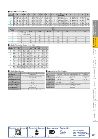
QExternal Dimensions Table
          Cylinder                                               P1
          I.D. (mm)  A  B  C  E  E1  F  H  I  K  L  M  N1 N2  R  S  T  V  W  One-Sided Through Hole  P2  P3  P4  P5  P6  P7
            6   58.5 13.5 45  13  10 26  8  16  28  35  14 24.5 6.5 4.5 37  16  4  -  6.5 Depth 3.3 3.4  -  M3 M3 Through Hole M  3 M3 Depth 4.5
            10  72  17  55  20  20 36.5  9  20  35  44  15 30  8  3.5 46  17  6  -  6.5 Depth 3.3 3.4 M4 Depth 7  M4 M3 Through Hole M  5 M3 Depth 5  M5
            16  79  19  60  30  30 46.5  9  25  45  56  18 38  8  5  58  20  8  -  8.0 Depth 4.4 4.3 M5 Depth 8  M5 M4 Through Hole M  6 M4 Depth 5  Depth
 14         20  112  24  70  30  - - -  52  12  28  50  62  23 46  10 9 9  11.5 98  25  10  9.5 9.5 Depth 5.3 5.2 M6 Depth 10  M5 M4 Depth 6 M  8 M4 Depth 7  G1/8  14
                                                                                            4.5
                94
                                                  6.5 64
            25
                                12
                             61
                                                              11 Depth 6.3 6.8 M8 Depth 12 M6 M5 Depth 7.5 M  8 M5 Depth 7
                                  35
                96
                  24
                        30
                     72
                                                    80
                                                  9
                                       78
                                                       30
                                                         12 13
                                          28 43
                                     60
 Air Cylinders / Valves / Regulators /   Shock Absorbers / O-Rings  Cylinder I.D.   10~25 D1=13+Stroke 30~50  60~80  90~100  Stroke  125  150  175  200  Shock Absorbers / O-Rings  Air Cylinders / Valves / Regulators /
            32
                                                       38
                  30
                                          36 53
                                14
                                     75
                                                         16 20
                                  44
                             73
                                                              11 Depth 6.3 6.8 M8 Depth 12 M6 M5 Depth 8 M10 M5 Depth 7
                     82
                        30
                                       96
                                                                                            G1/8
                                                        D(D1)
             (mm)
                        D=10+Stroke×0.5
              6
                                                              -
                                                    -
                                                                                           -
                                                                                 -
                                           -
                                                                        -
              10
                                                                                           -
                                          50
                                                    60
                       30
                                 40
                                                                        -
                                                                                 -
                                                              -
 Cylinders and   Accessories  16  25  35  45        55        65       75       145       145      Accessories  Cylinders and
              20
                       30
                                                                       80
                                                                                          100
                                          60
                                                    60
                                                                                100
                                                              80
                                 40
              25
                                                              80
                                                                                          100
                                          60
                                                    60
                                 40
                       30
                                                                       80
                                                                                100
              32
                                 50
                                                                                          110
                                                                       90
                                                              90
                                                    70
                                                                                110
                                          70
                       40
 P.951    QCylinder Theoretical Output Force Table                                                 P.951
                                 Air pressure (MPa)
          Cylinder  Operating  Compression area
          I.D. (mm)  Push  (mm 2 )  0.1   0.2   0.3   0.4   0.5   0.6   0.7
                Type
                    56.5
                                 17.0
                                                  39.6
                             11.3
                                             33.9
                          5.7
                                         28.3
                                     22.6
 Shock   Absorber  10  Push  157.1   15.7   31.4   47.1   12.6   15.7   18.8   110.0               Absorber  Shock
            6
                                                  22.0
                              6.3
               Pull
                                  9.4
                          3.1
                    31.4
                                             94.2
                                     62.8
                                         78.5
               Pull
                                                  70.4
                         40.2
                    402.1
                             80.4  120.6  160.8  201.1  241.3
 P.991     16  Push  100.5   10.1   20.1   30.2   40.2   50.3   60.3   281.5                       P.991
                                                 211.1
                    301.6
                             60.3
               Pull
                         30.2
                                 90.5  120.6  150.8  181.0
                         62.8  125.7  188.5  251.3  314.2  377.0
               Push
                    628.3
                                                 439.8
 Rod End   Bearings  20  Push  471.2   47.1   94.2  141.4  188.5  235.6  282.7   329.9             Bearings  Rod End
               Pull
                    981.7
                         98.2  196.3  294.5  392.7  490.9  589.0
                                                 687.2
           25
                    755.6
               Pull
                                                 528.9
                         75.6  151.1  226.7  302.2  377.8  453.3
 P.999     32  Push  1608.5   160.8  321.7  482.5  643.4  804.2  965.1  1125.9                     P.999
                   1206.4
                                                 844.5
               Pull
                        120.6  241.3  361.9  482.5  603.2  723.8
 Floating Joint  QCylinder Specifications 6  Double Acting  25~32  QMagnetic Switch Specification  PNP 3-Wire Type  Reed Sensor  Floating Joint
            Cylinder I.D. (mm)
                                                                    Electronic Sensor
                                  10~20
                                                  Item
                                                 Type
                                                                     NPN 3-Wire Type
                                                                                        2-Wire Type
          Operating Type
                                                             2-Wire Type
                                                             10V~28V DC
                                                                           5V~30V DC
                                                                                         100mA
                                0.15~1 (22~145)
          Operating Pressure Range Mpa(psi)
                                                 Max. Switching Current
 P.1004   Fluid Used     Air (filtered through the filter screen of 40 μm)  Voltage  2.5mA~100mA  30/200mA Max.  5V~240V AC/DC  P.1004
          Guaranteed Pressure Resistance Mpa(psi)  1.5(215)  Max. Contact Capacity  2.8W Max.  6W Max.  10W Max.
          Operating Temperature °C  -20~70       Internal Consumption Current  3mA Max.  5mA Max.  -
 Silencer  Operating Speed Range mm/s  +1.0 -5~0  +1.5  Leakage Current  Power polarity reverse protection, surge absorption protection  - -  Silencer
                                                             0.05mA Max.
                                  30~500
                                                                          0.01mA Max.
                                                 Protection Circuit
          Adjustable Stroke (mm)
                                                                           -10°C~70°C
          Stroke Tolerance Range
                                                 Protection Rating
                                Anti-collision pad
          Cushion Mechanism    0~100 0  >0~100 0   Operating Temperature  General IP64
 P.1006   Non-rotating Accuracy  ±0.2°  ±0.15°  ±0.1°                                              P.1006
 Control Valves   and Accessories                                                                  and Accessories  Control Valves
 P.1007                                                                                            P.1007
 Air Source   Handling                                                                             Handling  Air Source
 P.1015                                                                                            P.1015
 O-Rings                                                                                            O-Rings
 P.1027                                                                                            P.1027
           Register an Account  Technical Support  Sales Inquiry  Contact Us:
                                                                Tel:          (65) 6733 7211
                                                                Website:      sg.misumi-ec.com
                                                                Hours:        9am - 6pm (Mon - Fri)  964
            bit.ly/RegisterMISUMIaccount  techsupport@misumi.com.sg  cs@misumi.com.sg     9am - 3pm (Sat)
   964   965   966   967   968   969   970   971   972   973   974