Page 402 - MISUMI SINGAPORE Economy Series
P. 402

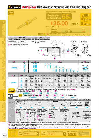
Ball Splines Key Provided Straight Nut, One End Stepped


           New                                   Representative model: E-BSDS16-300-P6-F30
          Products
                                                  Save Up to
                                                  vs Standard Type  55%              Shipping
                                                                                        from
    2                                                135.00                SGD 8 days                                                                                                                      2
    Linear Guides / Linear Bushings /    Ball Splines / Oil Free Bushings  Volume Discount  Unit Price  20%                                                                                               Ball Splines / Oil Free Bushings  Linear Guides / Linear Bushings /

                                                      Quantity
                                                                       1~9
                                                                                       10~
                                                      Discount
                                                 E  Shipping days may differ by Quantity.
          Accuracy  Type Material Hardness Surface Treatment Type  Material  Nut  E Quantity of volume discount above is for representative Part No. It may differ by the Part.
                     Spline shaft
           grade
                                           Hardness Surface Treatment
    Miniature   Linear Guides  Grade N Solid  Equivalent to    58HRC~  -  Straight  Equivalent to   58HRC~  -  2-r  L3  b  h  D=8~20  D=25~30                                                             Linear Guides  Miniature
                   SUJ2
                                     SCR420
   P.309  EThis product includes flat keys.               L3               bH8   t  +0.05   0  bH8  t  +0.05   0                                                                                          P.309
    Linear Guides for     Medium and Heavy Load  D1  4P  5F             2Dh8    1- φ u     1- φ u                                                                                                          Medium and Heavy Load  Linear Guides for


                                                          L1
   P.321                                                 3L L2                  Oil Hole   Oil Hole                                                                                                       P.321
    Cross Roller   Guides  Type  Dh8  1mm increments  4 4  5 5  6 6  8  Selection    1mm increments                                                                                                       Guides  Cross Roller
                                    3L
                                                                                        5F
                         2
               1
                                                              4P
                          8
                                   60~300
                                   60~400
                         10
                                                                                       2≤F≤16
                                                          10
                                   70~600
                         16
   P.337     E-BSDS      13        60~400         5 5  6 6  8 8 8 8  10  12  13  15  16  20  When P=4,                                                                                                    P.337
                                                                                      When P≥5,
                         20
                                                              12
                                                                  13
                                                          10
                                   80~700
                                                                                       2≤F≤P×5
    Linear Guide   Shafts  1Type  2Dh8  30  D1  100~900  L2  L3  bH8  h  r  t  u 10 Dynamic Ct Static C0t  Dynamic C  Static C0   Allowable Static Moment                                                 Shafts  Linear Guide
                         25
                                                                  13
                                   90~900
                                                                         16
                                                                     15
                                                              12
                                                          10
                                                                         16
                                                              12
                                                                     15
                                                                                25
                                                                  13
                                                                             20
                                                                        Basic Load Rating
                                                            Basic Rated Torque
                                                                                            M02
                                                                                     M01
                                      L1
                                0
                                                                         0.8
                                                              3.3
                                                                                      3.5
                                                                    6
                                                                                           25.2
                                                                               1.4
   P.341               8   16  Tolerance  27 15.7 10.5 2.5  2.5 1.25 1.2  (N·m)  (N·m)  (kN)  (kN)  (N·m)  (N·m)                                                                                          P.341
                                -0.027
                                                                                           85.3
                      10   21   -0.033  33  20  13  3  3  1.5  1.5  1.5  13.3  23.8  2.6  3.9  9.5  124.6
                                0
                      13
                                           15
                                        23
                                      36
                                                                   36.4
                           24
                                                                                      15
                                                             19.6
                                                                               5.4
                                                                         3.2
    Linear   Bushings  E-BSDS  16  31  -0.039  50  34 17.5 3.5  3.5 1.75  2.5  2 3  135.1  107.8  4.3  10.7  103.5  685.9                                                                                 Bushings  Linear
                                                                                            260
                                                                               7.7
                                                             35.7
                                                                   65.1
                                                       2
                                                                                     37.1
                      20
                                                                         5.9
                                                                                            380
                                                                                     55.3
                           35
                                      56 39.7 29
                                                             59.5
                                0
                                                    2
                                                 4
                                      71 50.3 36
                      25
                           42
                                                                          10
                                                                                15
                                              4
                                                                   243.6
                                                                          11
                      30
                                      80
                                        60
                                           42
                                                             190.4
                           47
                                                                   343
   P.349  Ordering  Please order after selecting part number and parameters according to the selection steps 1 to 5. 19.6  148.4  932.7                                                                   P.349
          Example  Part Number (1Type · 2D)  - -  3L  - -  4P  - -  5F
     Ball Spline  Alteration  Ordering  Part Number (1Type · 2D)  - -  3L  - -  4P  - -  F30  - -  (SC·FC...etc.)                                                                                          Ball Spline
                         E-BSDS16
                                                  P6
                                          300
                                                          F30
                                                                 5F
                     Example
                                                 300
                               E-BSDS16
                                                         P6
                                                                           SC10
   P.386         1Addition of wrench flat machining 2Addition of set screw flat 3Addition of Shaft End Keyway Machining 4Addition of Retaining Ring Groove Machining 5Addition of Tapped Hole Machining  6Addition of Nuts  7Addition of Surface Treatment  P.386
                                A  FC                                M                   plating
                                                                                         Nickel
          Alterations
    Oil Free   Bushings  SC  Y l1  W  Y  h  PKC        m          M×2           L        yellow)                                                                                                          Bushings  Oil Free
                                                                                         (light
                                                       TA
                                                                   MC
            Code
                                                        TA
                      SC
                                            PKC
                                 FC
                 Addition of wrench flat machining. Addition of set screw flat. Addition of keyway   Addition of retaining   Addition of tapped   NTW  NKR
   P.409         SC = 1mm increments  Method FC10-A8  machining at 1 place   ring groove   hole machining on   Add 1 nut    The surfaces of                                                               P.409
                                                               right end face
                                        on the shaft end P
                                                    machining.
                            FC, A = 1mm increments
                 ESC+l1≤Y
    Shaft Supports    Shaft Collars  Spec.  10 13 16 20 D 8  W 11 7 8  l1 8  EFC≤3×D  10 D 8  h 1  Method  PKC10  TA=1mm increments   D 10 13 16 20 8  6·8·10  (With 1 nut added,     are nickel plated   Shaft Collars  Shaft Supports
                                        part.
                                                                                         spline shaft
                                                    Method  TA10
                                                                             of the same
                                                                     M
                                                                                         and nut
                                                                    3·4
                                                                             specifications
                            EWhen 1.5×D<FC,
                                        EP≥8
                                                                    3·4·5
                                                    EP≥6
                              FC≤Y/2
                                    13
                                                                    5·6
                                        E PKC=
                                                                                       (Film thickness:
                                                    E4≤TA<F/2
                                    16
                         10
                      14
                                                                            there are 2 nuts)
                                                                    6·8
                            EA=0 or
                                         1mm increments
                                                                                         above 1μ)
                      17
                                    20
                                         PKC≤F-1
                                    30
                                                                    8·10·12
                      27
   P.430           25 30  22  15  A≥2  25  2  E PKC≤P×3          25 30  6·8·10·12                                                                                                                         P.430
          E  Only one of 3 and 4 can be selected. E6When is configured, there is no guarantee that the keyway positions of the 2 nuts are concentric.
          E7When is configured, the surface will be light yellow and there may be a color difference. Due to the surface treatment process, the following parts are more susceptible to rust.
            -Cut section  -Groove part  -Cut section  -Tapped part
          E  The relative positions of the grooves of spline shaft, the keyways and oil holes of nuts, and all the alterations (wrench flat, set screw flat, etc.) in the 3D model are for
           reference only and may differ from their actual positions.
          How to search  Search on MISUMI official website    Step 1   Input Search Keyword  Step 2   Select Brand Brand
           on website  By                    By                                     MISUMI
                    Type  E-BSDS            Keyword  ball spline
    397                                                                               Economy series
   397   398   399   400   401   402   403   404   405   406   407