
Page 307 - MISUMI SINGAPORE Economy Series
P. 307
1 1
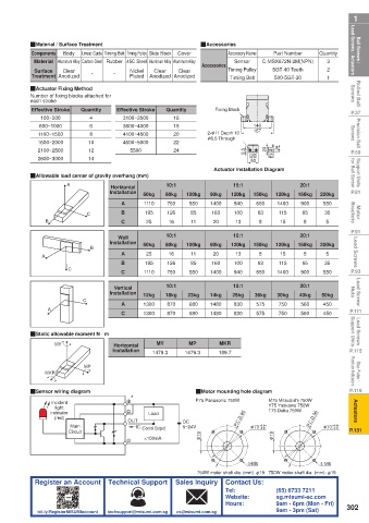
Ball Screws / Lead Screws / Actuators QMaterial / Surface Treatment Nickel Clear Cover QAccessories Sensor C-MSX672N-2M(NPN) Quantity Lead Screws / Actuators Ball Screws /
Part Number
Accessory Name
Components
Linear Guide Timing Belt Timing Pulley Slide Block
Body
3
Material Aluminum Alloy Carbon Steel Rubber 45C Steel Aluminum Alloy Aluminum Alloy
Accessories
2
5GT-40 Teeth
Timing Pulley
Clear
Surface
Clear
Treatment Anodized
Rolled Ball Screws QActuator Fixing Method - - Plated Anodized Anodized Timing Belt 500-5GT-30 1 Screws Rolled Ball
Number of fixing blocks attached for
each stroke
P.37 Effective Stroke Quantity Effective Stroke Quantity Fixing Block P.37
100~500
3100~3500
4
16
Precision Ball Screws 1100~1500 10 3600~4000 18 φ 6.5 Through 140 Screws Precision Ball
6
600~1000
157
2- φ 11 Depth 10
8
4100~4500
20
22
4600~5000
1600~2000
P.59 2100~2500 12 5500 24 8.5 30 23 25 34 P.59
14
2600~3000
Support Units for Ball Screw QAllowable load center of gravity overhang (mm) Actuator Installation Diagram for Ball Screw Support Units
50
15:1
20:1
10:1
Horizontal
P.81 A Installation 60kg 80kg 100kg 90kg 120kg 150kg 120kg 160kg 200kg P.81
Motor Brackets B C A 1110 750 550 1400 940 650 1400 900 550 Brackets Motor
126
35
195
63
85
160
115
100
65
B
11
8
16
5
8
13
20
15
25
C
P.91 Wall 10:1 15:1 20:1 P.91
Lead Screws A B Installation 60kg 80kg 100kg 90kg 120kg 150kg 120kg 160kg 200kg Lead Screws
A
8
20
5
11
25
8
16
15
13
63
160
195
35
65
115
85
P.93 C B 1110 126 550 1400 100 650 1400 900 550 P.93
940
C
750
Lead Screw Nuts C Installation 12kg 18kg 23kg 14kg 25kg 36kg 30kg 40kg 50kg Nuts Lead Screw
20:1
10:1
15:1
Vertical
P.111 A A 1300 870 680 1480 830 575 750 560 450 P.111
575
450
750
560
680
1480
870
C
1300
830
Lead Screws Support Units QStatic allowable moment N · m Support Units Lead Screws
MY
MP
MKR
Horizontal
P.115 MY Installation 1479.3 1479.3 189.7 P.115
Stop Plates / Position Indicators MKR MP Position Indicators Stop Plates /
P.119 QSensor wiring diagram QMotor mounting hole diagram P.119
* P75 Panasonic 750W M75 Mitsubishi 750W
Incident
Actuators indicator Load P.C.D.90 Y75 Yaskawa 750W P.C.D.90 Actuators
light
T75 Delta 750W
(red)
Main OUT IC DC φ 70 +0.01 φ 70 +0.01
5~24V
+0.04
+0.04
P.131 Circuit (Control Output) P.131
<100mA φ 19 φ 19
4-M5 4-M6
750W motor shaft dia. (mm): φ19 750W motor shaft dia. (mm): φ19
Register an Account Technical Support Sales Inquiry Contact Us:
Tel: (65) 6733 7211
Website: sg.misumi-ec.com
Hours: 9am - 6pm (Mon - Fri) 302
bit.ly/RegisterMISUMIaccount techsupport@misumi.com.sg cs@misumi.com.sg 9am - 3pm (Sat)