Page 1603 - MISUMI SINGAPORE Economy Series
P. 1603

[Technical Data]
            Toothed Pulleys               Excerpts from JIS B 1856(1993)


          1.Dimensions of the Rack for the Cutter and the Tolerances

                                    Pt
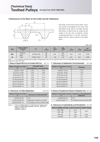
                       A      A                               The pulley should have involute tooth, which
                                                              are created and shaped by the cutter. The
                                                              dimensions of the rack for the cutter and the
                                                              tolerances as determined by analyzing the
                a
                                                              shape of the rack with a projector, shape
                hr                    r2                      measuring instrument or the like, should be
                                                              agreed with the relevant figures in the table
                          b g            r1                   below.

                                                                                         Unit: mm
                    Number of Teeth of                   hr      bg                       2a (1)
            Type      the Pulley     Pt         A      +0.05    +0.05     r1      r2
                        Z                      Ú0.12     0       0      Ú0.03    Ú0.03  (Reference)
                     10≤Z≤23                    28B              0.61
            MXL                   2.032Ú0.008           0.64             0.30     0.23    0.508
                     24≤Z                       20B              0.67
             XL      10≤Z         5.080Ú0.010   25B     1.40     1.27    0.61     0.61    0.508
          Note (  ) : a is a measurement indicating the position corresponding to the pitch line (Centerline of the Core Line of the Belt) of the belt corresponding to the
              1
          shape of the rack for the cutter.
          2. Tolerance of Adjacent Pitch Error and Cumulative Pitch Error  Unit: mm  4. Tolerances of Addendum Circle Diameter   Unit: mm
           Addendum Circle Diameter of Pulley  Allowable Value  Addendum Circle Diameter of Pulley  Tolerance
                  d0         Tolerance of Adjacent Pitch Error Accumulated Pitch Error  d0
               5.96≤d0≤  25.40   0.03       0.05             5.96≤d0≤  25.40       +0.05
                                                                                     0
               25.40<d0≤  50.80  0.03       0.08            25.40<d0≤  50.80       +0.08
                                                                                     0
               50.80<d0≤101.60   0.03       0.10            50.80<d0≤101.60        +0.10
                                                                                     0
              101.60<d0≤177.80   0.05       0.13           101.60<d0≤177.80        +0.13
                                                                                     0
              177.80<d0≤304.80   0.05       0.15           177.80<d0≤304.80        +0.15
                                                                                     0
              304.80<d0≤508.00   0.08       0.18           304.80<d0≤508.00        +0.18
                                                                                     0
              508.00<d0≤762.00   0.08       0.20           508.00<d0≤762.00        +0.20
                                                                                     0
              762.00<d0≤967.16   0.08       0.23           762.00<d0≤967.16        +0.23
                                                                                     0
          3. Tolerance of Side Deflection    Unit: mm  5. Tolerance of Circumferential Deflection of Addendum Circle  Unit: mm
           Addendum Circle Diameter of Pulley    ( 2 )  Addendum Circle Diameter of Pulley  Tolerance of Circumferential
                              Tolerance of Deflection(TIR)
                  d0                                            d0                Deflection
               5.96≤d0≤101.60  0.10                          5.96≤d0≤203.20  0.13
              101.60<d0≤254.00  Addendum Circle Dia. d0×0.001  203.20<d0≤967.16  0.13+〔(Addendum Circle Dia. d0-203.20)×0.0005〕
              254.00<d0≤967.16  0.25+〔(Addendum Circle Dia. d0-254.00)×0.0005〕
              2
          Note (  ) :  TIR is an abbreviation for Total Indicator Reading and   6. Tolerance of Cylindricity and Parallelism  Unit: mm
                refers to the difference between the max. deflection
                reading and the min.                   Nominal Widths of Pulley  Cylindricity Tolerance Parallelism Tolerance
                deflection reading.
                                                            025~050          0.01        0.03
                                                            075~150          0.02
                                                             200·300         0.04        0.04
                                                             400·500         0.06        0.05


 1597                                                                                             1598
   1598   1599   1600   1601   1602   1603   1604   1605   1606   1607   1608