
Page 1606 - MISUMI SINGAPORE Economy Series
P. 1606
[Technical Data]
Designing of Chain Drive Mechanism 2
Q Specification Selection for Low-Speed Operation Q Specification Selection for Low-Speed Operation with Impact Load
In operations using a chain speed of 50 m/min. or less, chain elongation due In operations with a great amount of impact loading due to frequent
2
to wear can almost be ignored. Under such low-speed conditions, the service startups, stops, reversing, or braking, the inertia(GD )of the prime
life of the chain largely depends on its fatigue strength. Low-speed operation mover and the driven machine needs to be taken into account.
is more economical than operation under "normal conditions". Low speed is Under such conditions, exercise extreme caution, as the chain can be
recommended for operations with fewer startups and stops that enable smooth subjected to loads much greater than in operation under normal conditions.
power transmission. Selection of ambient atmosphere, layout, lubrication, etc. for Select the chain using the following formula.
low-speed operation is the same as that for operation under normal conditions.
Selection should be made in accordance with the following formula. Max. Allowable Load Acting on Chain as Impact Speed
Load of Chain ≥ Calculated from the Starting x Coefficient x Coefficient
Max. Allowable Max. Tension N Application Coefficient Speed Coefficient N Torque of the Prime Mover (Table 5) (Table 4)
Tension of Chain ≥ Working on Chain x (Table 1) x (Table 4)
P.1599
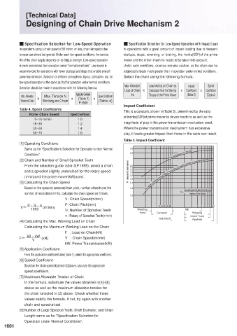
Impact Coefficient
Table 4. Speed Coefficients This is a constant, shown in(Table 5), determined by the ratio
Roller Chain Speed Speed Coefficient of inertia(GD )of prime mover to driven machine as well as the
2
0~15 m/min 1.0
15~30 1.2 magnitude of play in the power transmission mechanism used.
30~50 1.4 When the power transmission mechanism has excessive
50~70 1.6 play, it loads greater impact than those in the table can result.
Table 5. Impact Coefficient
[1] Operating Conditions
Same as for "Specifications Selection for Operation under Normal 3.0
Conditions" 2.5 The mechanism has the play.
[2] Chain and Number of Small Sprocket Teeth
From the selection guide table 3(P.1599), select a chain 2.0
1.5
and a sprocket slightly undersized for the rotary speed Impact Coefficient 1.0
0.8
(r/min)and the prime mover(kW)used. 0.6 The power transmission mechanism has no play by sagging of chain or something like that.
K 0.5
[3] Calculating the Chain Speed 0.4
Based on the sprocket selected(chain pitch, number of teeth)and the 0.3 Converted Inertia of the Motor Shaft of the Load
number of revolutions(r/min), calculate the chain speed as follows. R= Inertia of the Motor
0.2
V : Chain Speed(m/min)
V= P · N · n (m/min) P: Chain Pitch(mm) Winching 0.5 0.6 0.8 2 Mill 3 4 5 6 8 10
1000
N: Number of Sprocket Teeth
Rollgang
n : Rotary of Sprocket Teeth(r/min) Hoist Conveyor Crane Truck
[4] Calculating the Max. Working Load on Chain Inertia Ratio R Flywheel
Calculating the Maximum Working Load on the Chain
F : Load on Chain(kN)
F= 60 · kW (kN) V : Chain Speed(m/min)
V
kW: Power Transmission(kW)
[5] Application Coefficient
From the application coefficient table(Table 1), select the appropriate coefficient.
[6] Speed Coefficient
Based on the chain speed obtained in[3]above, calculate the appropriate
speed coefficient.
[7] Maximum Allowable Tension of Chain
In the formula, substitute the values obtained in[4]~[6]
above as well as the maximum allowable tension for
the chain selected in [2] above. Check whether these
values satisfy the formula. If not, try again with another
chain and sprocket set.
[8] Number of Large Sprocket Teeth, Shaft Diameter, and Chain
Length same as for "Specification Selection for
Operation under Normal Conditions".
1601 1602