
Page 1281 - MISUMI SINGAPORE Economy Series
P. 1281
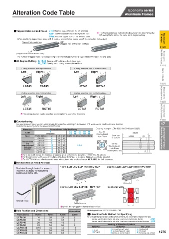
Economy series  Alteration Method _ Built-in Connector Method  Alteration Code Table  Economy series
 Aluminum Frames                                                             Aluminum Frames


          QTapped Holes on End Faces LTP: Machine tapped hole on the left end face  E  The frame placement method is the benchmark for determining the
 Aluminum   Frames  · When machining tapped holes along with D holes or wrench holes, please specify their direction (left or right).  Frames  Aluminum
                               RTP: Machine tapped hole on the right end face
                                                              left and right of a frame, the same as 45-degree cutting.
                               TPW: Machine tapped hole on the two end faces
               Tapped hole machining
                                      RTP
 P.1183           LTP                 (Tapped hole on the right end face)                          P.1183
 Brackets / Corners /    Sheet Metals / Connectors  (Tapped hole on the left end face)             Sheet Metals / Connectors  Brackets / Corners /
           The number of tapped holes varies depending on the frame type (number of tapped bottom holes on the end face).

                        R#T45: Specify a 45° cutting on the right end face.
 P.1215   Q45-Degree Cutting  L#T45: Specify a 45° cutting on the left end face.                   P.1215
              Cutting a section from top to bottom
                                              Cutting a section from outside to inside
 Nuts / Bolts  Left  L  Right L               Left  L    Right  L                                   Nuts / Bolts

 P.1243        LAT45     RAT45                   LBT45      RBT45                                  P.1243
 Decorative   Accessories  Left  Right        Left      Right  L                                   Accessories  Decorative
                                              Cutting a section from inside to outside
              Cutting a section from bottom to top
 P.1258           L           L                   L                                                P.1258
 Panel Fasteners / Panels /    Door Sliding Slot Accessories  EThe cutting direction can be specified according to the above four directions.  RDT45  Door Sliding Slot Accessories  Panel Fasteners / Panels /
               LCT45
                                                 LDT45
                           RCT45
 P.1262   QCounterboring                                                                           P.1262
 17        For counterbored holes, you can select a hole diameter after selecting Z. A maximum of 5 holes can be machined in one direction.  17
           Refer to the above figure for the placement of frames.  XA    XB    XC    XD    XE  Ordering example: LCF8-3030-500-Z6-XA200-XB256
 Aluminum Frames /   Related Accessories  Instructions   Frame Series Selection  11  6.6  Distance from left end (0.5mm increments)   Counterbored   to bottom)  XA200 XB256  Z6  d  Related Accessories  Aluminum Frames /
               Alterations
                                Counterbored Hole Machining
                                                              XA~XE
                               Z
                 Code
                                           YA    YB    YC    YD    YE
                                                                     (from top
                                     d
                Spec.
                                Z
                                        d1
                                                             Hole Plane
                                6
                        LCF6-20
                        LCF8-30
                                8
                                    14
                                        9
                        LCF8-40
                                    14
                                        9
                                8
                 for
                                                                     YA~YE
              counterbored
                        LCF8-50
                                                                   Counterbored
                hole and
                                        13
                                    19
                                12
                       LCF10-45
                                                                    Hole Plane
                position
                                        13
                                    19
                       LCF10-50
                                12
                                12
                                        13
                       LCF10-60  12  19  13     7~L-7              (from right to left)  L  d1
                                    19
              EFor a slot width series, the multiples of spacing are a uniform size. [Example: 10-100100(=10-50 size)
              EFor the same slot width series or multiples of a, the Z dimension is fixed and does not need to be selected.
              EFor LCFT8-3030 and other types of frames with a plane, refer to alterations on D P.1275 for their placement.
          QWrench Hole at Fixed Position
                                      1 row-LCH·LCV·LCP·RCH·RCV·RCP  2 rows-LWH·LWV·LWP·RWH·RWV·RWP
           Machine through holes for wrench
           insertion, suitable for fastening
           concealed joints, etc.
                                                                                    2-d
                                                     d
                                                   H                        H   J
                                      3 rows-LEH·LEV·LEP·REH·REV·REP  Sectional View
                                                         3-d
           Wrench Hole
                                              H  J  K
                                                                                �
                                      ESpecify the hole position from the left end face.
          QHole Position and Dimensions    Wrench Hole  Ordering example: LCF8-3030-500-LCH
           Frame Series  H(mm)  J(mm)  K(mm)  d(mm)   QAlteration Code Method for Specifying
           LCF6-20      10     20     20      5       For a hole alteration combination, use the symbols for the 1st, 2nd and 3rd letters indicated in the table.
           LCF8-30      15     30     30      7          Machine wrench holes on the left side of the 2-row frame in the horizontal direction.    -LWH
           LCF8-40      20     40     40      7          Machine wrench holes on the left side of the 2-row frame in horizontal and vertical directions.   -LWP
           LCF8-50      25     50     50      9                    Meaning of Alteration Symbols
                                                                        2nd Letter
                                                                                       3rd Letter
           LCF10-45    22.5    45     45      10         1st Letter  C (1 row of wrench holes)  H (Horizontal)
           LCF10-50     25     50     50      10         L (Left)    W (2 rows of wrench holes)  V (Vertical)  1276
           LCF10-60     30     60     60      10         R (Right)   E (3 rows of wrench holes)  P (Horizontal and vertical)