
Page 1613 - MISUMI SINGAPORE Economy Series
P. 1613
[Technical Data]
Selection of Flat Belts
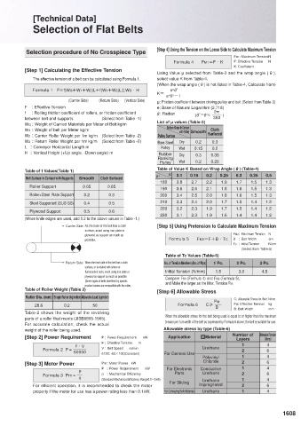
Selection procedure of No Crosspiece Type [Step 4] Using the Tension on the Loose Side to Calculate Maximum Tension
FM1: Maximum Tension N
Formula 4 FM1=F · K F: Effective Tension N
K: Coefficient
[Step 1] Calculating the Effective Tension
Using Value μ selected from Table-3 and the wrap angle ( ),
The effective tension of a belt can be calculated using Formula 1. select value K from Table-4.
(When the wrap angle ( ) is not listed in Table-4, Calculate from)
Formula 1 F=f(WG+W1+W2)L+f(W1+W3)L±WG · H e F'
μ
K=
e F ' -1
μ
(Carrier Side) (Return Side) (Vertical Side) μ: Friction coefficient between driving pulley and belt (Select from Table-3)
F : Effective Tension e: Base of Natural Logarithm (2.718)
f : Rolling friction coefficient of rollers, or friction coefficient ': Radian 2π
(F′=F× )
between belt and supports (Select from Table -1) 360
WG : Weight of Carried Materials per Meter of Belt kg/m List of μ values (Table-3)
W1 : Weight of belt per Meter kg/m Surface Shape in Contact Cloth
with Pulley Smooth
W2 : Carrier Roller Weight per 1m kg/m (Select from Table -2) Pulley Surface Surfaced
W3 : Return Roller Weight per 1m kg/m (Select from Table -2) Bare Steel Dry 0.2 0.3
L : Conveyor Horizontal Length m Pulley Wet 0.15 0.2
H : Vertical Height (+Up angle, -Down angle) m Rubber Dry 0.3 0.35
Ranking
Pulley Wet 0.2 0.25
Table of f Values(Table 1) Table of Value K Based on Wrap Angle ( ) (Table-4)
Belt Surface in Contact with Supports Smooth Cloth Surfaced F° μ 0.1 0.15 0.2 0.25 0.3 0.35 0.5
180 3.8 2.7 2.2 1.9 1.7 1.5 1.3
Roller Support 0.05 0.05 190 3.6 2.6 2.1 1.8 1.6 1.5 1.3
Roller+Steel Plate Support 0.2 0.3 200 3.4 2.5 2.0 1.8 1.6 1.5 1.3
Steel Supported (SUS·SS) 0.4 0.5 210 3.3 2.4 2.0 1.7 1.5 1.4 1.2
220 3.2 2.3 1.9 1.7 1.5 1.4 1.2
Plywood Support 0.5 0.6
230 3.1 2.3 1.9 1.6 1.4 1.4 1.2
(When knife edges are used, add 0.2 to the above values in Table -1.)
Carrier Side: As the back of the belt has a cloth [Step 5] Using Pretension to Calculate Maximum Tension
surface, avoid using iron plate or
plywood as support as much as FM2: Maximum Tension N
possible. Formula 5 FM2=F+B · TC B : Belt Width cm
TC : Initial Tension N/cm
(Select from Table-5)
Table of Tc Values (Table-5)
Return Side: When the front side of the belt has a cloth No. of Tension Members (No. of Plys) 1 Pc. 2 Pc. 3 Pc.
surface, or is coated with silicon or
fluorocarbon resin, avoid using iron plate or Initial Tension (N/mm) 1.5 3.0 4.5
plywood as support as much as possible. Compare FM1 (Formula 4) and FM2 (Formula 5),
(Some types of belts identified by specific and Make the larger as the Max. Tension FM.
product names are compatible with the roller,
Table of Roller Weight (Table 2) table.) [Step 6] Allowable Stress
Roller Dia. (mm) Single Roller (kg/roller) Allowable Load (kg/roller) C: Allowable Stress for Belt N/mm
FM
28.6 0.2 50 Formula 6 C≥ FM: Effective Tension kg
B
B: Belt Width
mm
Table-2 shows the weight of the revolving When the allowable stress for the belt being used is equal to or higher than the maximum
parts of a roller that meets (JISB8805-1965). tension per 1cm width of the belt as expressed by Formula 6 above, the belt is suitable for use.
For accurate calculation, check the actual
weight of the roller being used. Allowable stress by type (Table-6)
[Step 2] Power Requirement P : Power Requirement kW Application MMaterial Number of Allowable Tension
Layers
F : Effective Tension N (N/mm)
F ∙ V V : Belt Speed m/min Urethane 1 4
Formula 2 P = 2 6
60000 6120: 60×102(Constant) For General Use
Polyvinyl 1 4
[Step 3] Motor Power Pm: Motor Power kW Chloride 2 6
P : Power Requirement kW For Electronic Conductive 1 4
P J : Mechanical Efficiency Parts Urethane 2 6
Formula 3 Pm =
(Standard Mechanical Efficiency Range0.5~0.65) Urethane 1 4
For efficient operation, it is recommended to check the motor For Sliding Impregnated 2 6
property if the motor for use has a power rating less than 0.1kW. For Conveying Bulk Materials Urethane 1 4
1607 1608